Overview
This is the procedure for upgrading the 510 connector from the original simple type 510 connector to the spring-loaded, stainless-body type released 6/2014. This is in our opinion not a simple procedure and we do not recommend it if the option to have the shop handle it is at all practical. We are not liable for any issues arising from the application of this procedure by the end user.
Tools and supplies required
- Soldering iron (recommended variable temperature, 70+w, medium angled tip)
- Medium Phillips-head screwdriver (PH1)
- Solder & flux
- Flush cutters
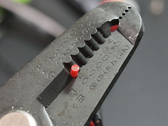
- Wire strippers (20 ga.)
- 14mm open-end wrench
- 510 upgrade kit from Protovapor
Procedure
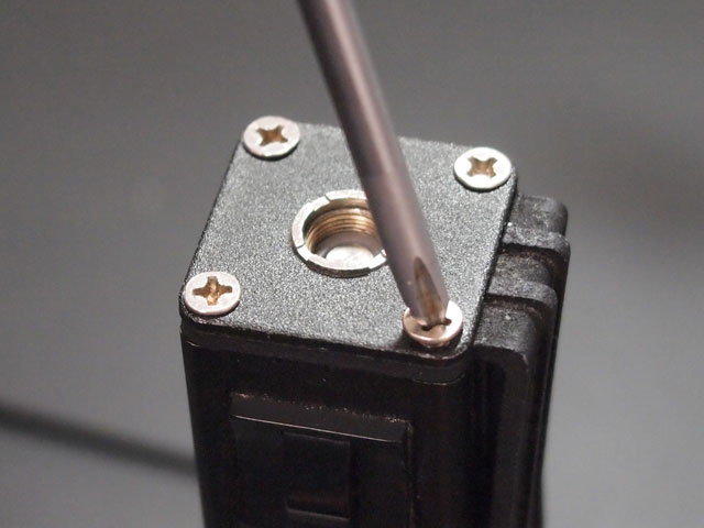
STEP 1: Remove top cover screws. You will not be reusing these screws.
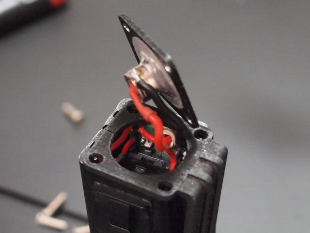
STEP 2: Lift cap clear and inspect atty wires. If the wires are broken, damaged, twisted into bunches, or otherwise not whole, the best course of action is to send the mod to Protovapor for the 510 installation. We will replace the atty wires for you. Otherwise, you will need to find a way to replace and/or repair them by splicing.
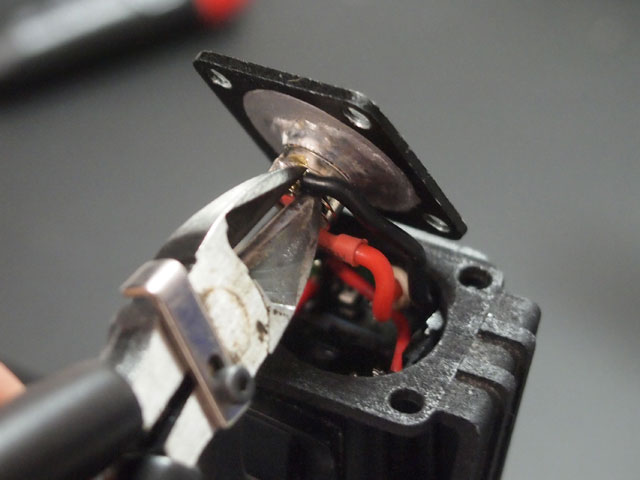
STEP 3: Clip the atty wires as close to the solder points on the original connector as possible. Leave as much length as you can.
STEP 4: Strip the positive atty lead, leaving about 5mm of bare wire exposed. Your wire may already have a long “tail” of bare wire under a heat shrink; preserve as much of that as you can, just clip off any solder. Twist the stranded end. Do NOT flux.
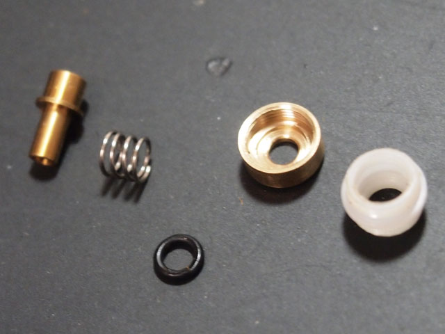
STEP 5: Disassemble connector core. The parts are, from left: Positive pin, pin spring, pin o-ring, bottom cap, delrin insulator. If the insulator has any delrin “strings” still on it from machining, pull those off.
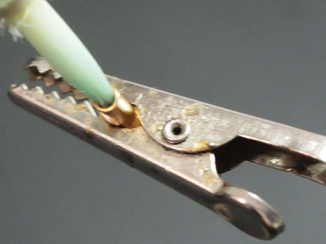
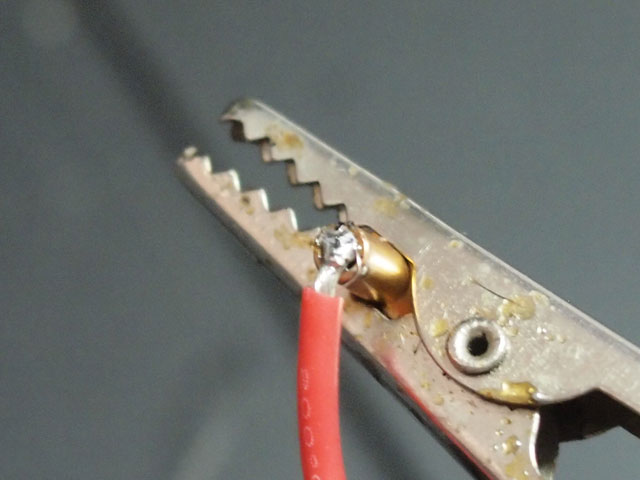
STEP 6: Secure the positive pin in a heat-resistant clip or clamp. Apply flux inside the bottom hole of the pin.
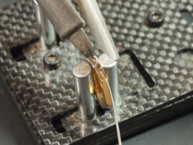
STEP 7: With tinned soldering iron at fairly high temperature (750°F+), heat the pin from inside the hole. Ideally solder from tinned tip begins to flow down into hole. When pin is heated, carefully feed solder into the cavity until 1/2 to 2/3 full. Note: Be careful not to get any solder on the outside of the pin. The outside of the pin must be clean for the pin to function properly when installed. If any solder gets out, desolder, scrape or sand it off.
STEP 8: Thread these core components onto the positive atty wire, in order: Bottom cap (cup facing up), o-ring, pin spring.

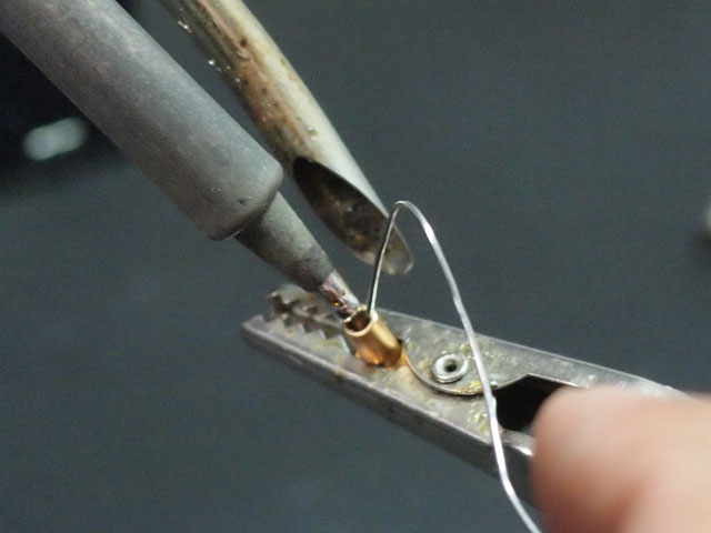
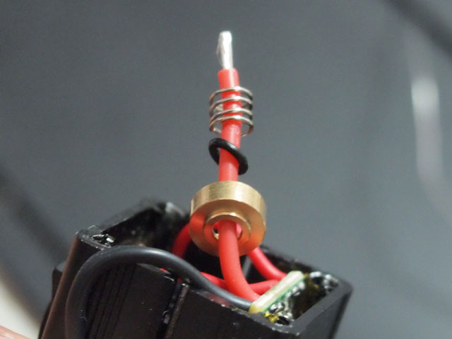
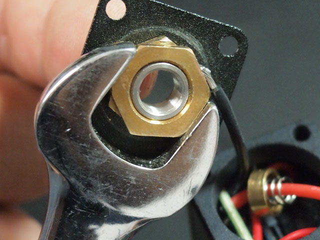
STEP 9: CRITICAL STEP. Twist the positive wire end fairly tight, and again, do not flux. Melt the solder inside the pin, keeping the soldering iron tip off to one side. When the solder has melted, insert the positive wire, ideally angled to one side of the pin (first image). Try to keep the solder low in the pin cavity and do not let it wick up the wire. Remove the iron and let it cool. Check connection. The goal is to have the positive solidly connected, with as little solder above the open end of the pin as possible (i.e. adding as little length to the pin as possible), with the wire able to bend easily 90 degrees at the connection, and no solder on the outside of the pin. If there is solder on the outside of the pin, sand or scrape it off. The results may not be pretty (as above :/), but as long as the wire is solidly connected and there isn’t excess solder, it will work. If there is too much of a “tail” of solder sticking out of the pin, you can clip it with the flush cutters.
STEP 10: Flux and tin one face of the negative jam nut. It may take a lot of heat to get the solder to stick here. You only need solder on about 1/2 of the face.
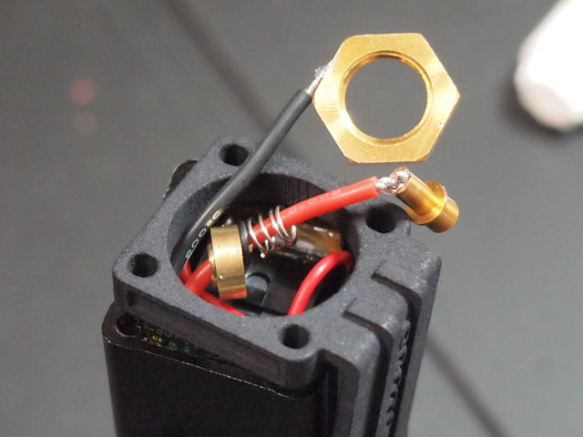
STEP 11: Strip, flux and tin the negative atty wire. Solder it to the negative jam nut as shown above. Try not to get solder on the top or bottom face of the nut. Place the clip and/or any spacers down over the atty wire assemblies.
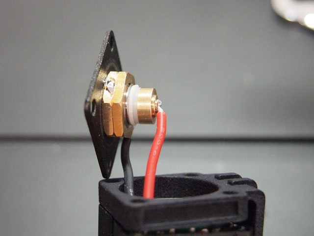
STEP 12: Using the 14mm open-end wrench, tighten the negative jam nut onto the connector body/top plate assembly. Hand-tight is ok. Note that the negative wire must be routed correctly to curve around the connector clockwise from the board connection. The solder point should end up near the front (button side) of the case.
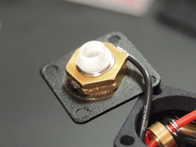
STEP 13: Screw the insulator finger-tight into the connector body.
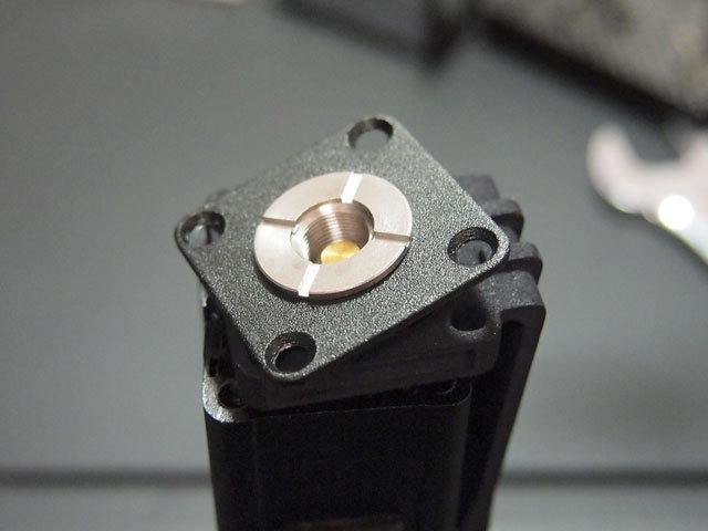
STEP 14: Assemble the core, placing the pin spring and o-ring onto the tail section of the pin, then pushing the pin through the hole in the bottom cap. The pin should be able to move freely through the hole in the bottom cap. Then screw the assembly onto the insulator. The bottom cap should turn freely and tighten down onto the insulator. Snug the whole core assembly finger tight. Bend the positive atty wire 90 degrees as shown; you will want it fairly tight up against the bottom of the cap.
STEP 15: Tuck the fire switch wires down into the mod on either side of the switch, to clear the area directly above the switch. With the board side toward you and button side facing away, curve both atty wires around the left side of the connector while lowering the top cap into place. The goal is to keep the negative wire fairly high around the negative jam nut, with the positive wire looping forward below and left of the connector. Make sure neither wire is trapped under the connector. Hold the top in position and test the pin travel. It should travel freely a little over 1mm. The first press or two may be slightly tighter as the positive wire settles into position.
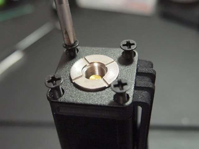
STEP 16: Using the new 14mm screws, start all four screws in the top of the mod. You may need to squeeze the halves of the case together to get them all started. Be careful not to cross-thread.
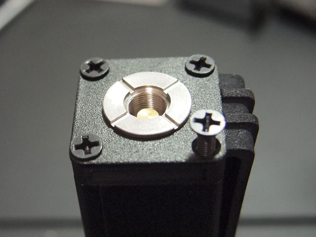
STEP 17: Tighten all screws gradually in a pattern so they all draw tight together (okay so the picture is not the best example). Adjust as necessary. Test and vape!